Computer-Assisted Gripper and Fixture Customization
via Rapid Prototyping
4. A basic approach to finger design
In this section, we introduce our computational approach in the context of designing gripper fingers for simple, parallel-jaw actuators. Such actuators, typically pneumatic, are common in industry due to their low cost, low weight, simplicity and high reliability. Through the use of customized fingertips, these simple actuators can be highly effective in achieving precise and reliable manipulation of complex parts.
While the remainder of this paper focuses on gripper designs, it should be recognized that the same approach applies to fixture designs, both passive and active.
4.1 Forming monolithic fingers
With the goal of achieving form closure in mind, let us consider how one can generate finger designs for a part to be manipulated using a parallel-jaw gripper. As a gross initial approximation, we can model each finger as a rectangular solid, or finger �blank.� These blanks will later be modified to suit the part geometry.
Some provision must be made for mounting the fingers onto the gripper jaws; hence, at least one face of each finger blank must contain predefined features such as alignment pins and screw holes. These would allow each finger to mate accurately with its corresponding gripper jaw.
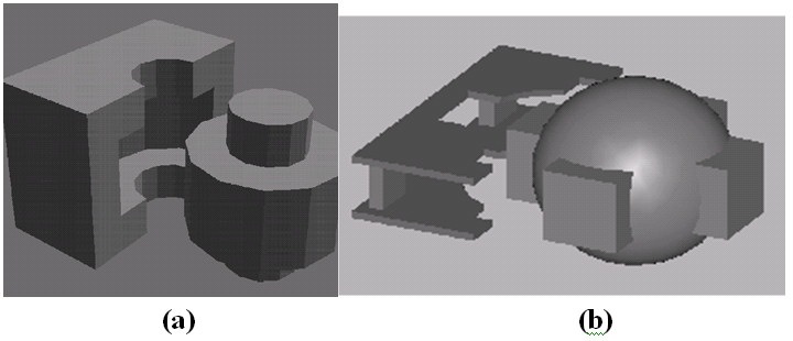
Figure 1a suggests a means by which the rest of the finger shape can be formed. By subtracting half of the example workpiece from the finger blank, we have formed a fixture that almost entirely constrains the object's movements. If a complementary finger is generated for the other half, then the workpiece is almost fully enclosed, in this case resulting in form closure.
4.2 Reducing fabrication time and cost
While the computational process suggested by Figure 1a is intuitive, it is unnecessarily detailed. Form closure for this part could be achieved using a minimum of two strategically-chosen, thin horizontal slices of the finger-block, illustrated in Figure a. Abstracting the gripper shape to planar layers is conveniently appropriate for fabrication using the CAM-LEM system. By cutting contours in a relatively small number of relatively thick sheets, the fabrication process becomes simpler and faster. Furthermore, this more skeletal design leaves the opportunity to expose critical surfaces, e.g. for grasp approach and/or required approach clearances for assembly operations. The chosen layers to be contoured can be assembled using mechanical spacers, as illustrated in Figure 1b.
By invoking this simplifying abstraction, we also open up the range of applicable methods for fabricating the constituent layers, including laser cutting (currently used in the CAM-LEM process), conventional CNC machining, CNC Electric Discharge Machining (EDM), water-jet cutting, plasma-torch cutting, and photo-chemical etching. The critical feature of the fabrication process is that it is computer controlled, and can be driven directly from the electronic description of the desired layer shape. Note, though, that while each layer can be fabricated using a 2-axis method, complex 3-D constraints are configurable through vertical-stack assembly of these simple layers.
An important consideration for the use of thick layers to assemble tooling is illustrated in Figure 2b, which shows the outlines of three adjacent coronal slices of a human head. Consider the case of a gripper-finger design to handle this part, where we presume use of a thick layer within the tool assembly that would contact all three of these cross sections. To be successful, this layer of tooling must be fabricated to accommodate the head's out-of-plane curvature. Conformal tooling could be fabricated, e.g. by using 5-axis machining. However, it is desirable to utilize simple 2-axis fabrication technologies. To accomplish this, we define a single, vertical-cut contour for each tooling layer. This contour is computed as the perimeter of the union of multiple part cross sections within the elevation range of the tooling layer in question. With reference to Figure 2, the three coronal slices illustrated can be combined into a single region through a Boolean �OR� operation. The perimeter of the resulting union of regions encloses each of individual contours. We use this resulting contour to generate the outline of the corresponding thick, 2.5-D gripper layer.
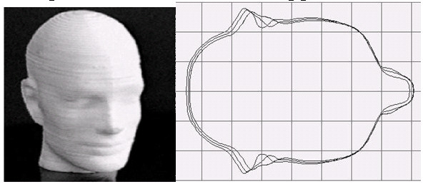
FIGURE 2: A TEST OBJECT AND THE SILHOUETTE OF A FINITE-THICKNESS SLICE, APPROXIMATED HERE BY MULTIPLE INFINITESIMAL SLICES
4.3 Finger construction for a sample part
To illustrate and validate our approach, gripper fingers were constructed for a reasonably complex test object. The test object was a ceramic model of a human head, shown in Figure 2a.
Our test fingers were fashioned out of 1.59 mm (1/16") Plexiglas® sheets. The example design invokes the sim-plifying abstraction suggested by Fig 2, utilizing only two thick-slice layers. Also, due to the significant curvature of the test object relative to the thickness of the finger sheets, the technique illustrated in Figure 2b needed to be invoked. The gripper's layer contours were computed based on the CAD description available for our test part, and the com-puted contours were laser-cut using the CAM-LEM system.
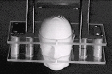
FIGURE 3: RP FINGERS HOLDING THE TEST OBJECT
The layer designs included pre-defined bolt-hole patterns for mechanical assembly and fastening to the gripper jaws. Stock mechanical spacers were used to offset the two layers. Available standard increments of such stock spacers were used to define the spacing of gripper layers when computing the finger contours from the part's CAD model. As a result, gripper fabrication only requires laser cutting the computed outlines, then bolting the fabricated layers to the pneumatic actuator. The entire process of fabrication, from CAD design to functional gripper, can be accomplished in minutes.
Our test gripper is shown in Figure 3. As expected, the fingers achieved precise form closure in grasping this complex part. In the present example, Plexiglas� was used, as its transparency helps to illustrate the approach. In practice, we expect to use low-friction polymers, such as Delrin® and Teflon®. These relatively tough materials offer low friction, a property that can be exploited to design grippers that are tolerant of part location uncertainties, as discussed in section 5.4.